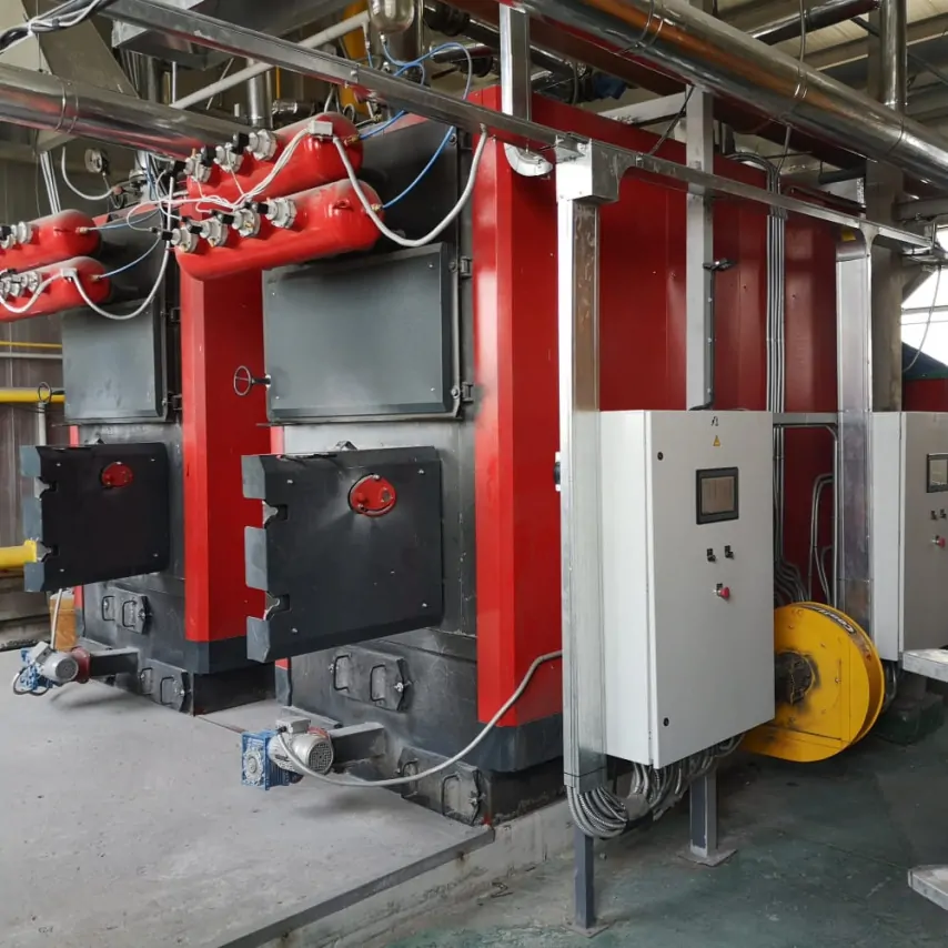
Hot-water modular boiler plant: thermal circuit, hydraulics and boiler protection
A hot-water modular boiler plant must not only generate the required amount of heat but also transfer it to consumers under every intended operating condition. If the thermal circuit does not reflect actual flow rates, the temperature schedule, network resistance and boiler limitations, correctly selected installed capacity alone will not guarantee stable operation.
The circuit arrangement, pumps, pressure-maintenance method, water treatment and protective control logic are determined from the input data for the specific facility. General engineering principles help to verify the concept, but they do not replace hydraulic calculations, equipment documentation and project-specific design.
Which parameters define the thermal circuit of a hot-water modular boiler plant
The first design input is not the combined boiler output but the heat-load profile. Maximum, minimum and intermediate loads, the duration of each operating condition, the heating season, domestic hot-water demand and any process consumers all need to be understood. This profile establishes the range over which the boiler plant must regulate its output.
The flow and return temperatures are then defined for design and part-load conditions. It is important to consider not only the winter peak but also operation with a small temperature difference or low flow rate. If the actual network schedule differs from the values used for equipment selection, the calculated flow, pump operating point and ability of the boilers to modulate reliably will also change.
The input data include permitted working pressures, differential pressure at the boiler plant interface, system elevations and the hydraulic resistance of the external network. For an existing facility, measured values under representative operating conditions are preferable to design values alone. They help distinguish resistance within the boiler plant from balancing or capacity problems in the distribution network.
The types of consumer and their connection arrangements are assessed separately. One circuit may serve ventilation equipment with a constant flow, another may supply radiator heating with control valves, while a third supplies a process heat exchanger. If these consumers have different temperature schedules and variable flow rates, the thermal circuit must prevent undesirable interaction between them.
The boiler type establishes the minimum permitted flow, return-temperature requirements, hydraulic resistance, thermal inertia and modulation range. These parameters are taken from the technical documentation for the selected model. A universal hot-water boiler piping arrangement that ignores the boiler design can cause excessive cycling, local overheating or unwanted condensation.
Before the modular boiler plant is detailed, the responsibility boundary between the plant and the external system must be defined. The design records the connection point, heat-transfer-medium parameters, permitted differential pressure, metering and control scope, and the party responsible for network regulation. Without this definition, pumps and protective functions may be selected for conditions that do not correspond to actual operation.
Boiler and distribution circuits: hydraulic calculation
Boilers and consumers may be connected directly, through headers, a hydraulic separator or a heat exchanger. These options do not form a ranking from basic to superior; they are different methods of coordinating flow rates, pressures, temperatures and water quality. Selection depends on the compatibility of the boiler circuit with the distribution network.
A direct connection may be justified when the circuits operate with compatible flows and pressures and the heat-transfer medium meets the boiler requirements. In this arrangement, the effect of consumer control valves on minimum boiler flow is particularly important. A change in one circuit must not force other circuits into an unstable operating condition.
A hydraulic separator reduces interaction between the pumps on the boiler and distribution sides. It can be useful when their flow rates change independently or when a boiler cascade serves several consumer circuits. However, a hydraulic separator is not mandatory in every boiler plant; its use must follow from the hydraulic design rather than from a standard schematic.
A header arrangement allows several branches to operate with their own pumps and controls. The design checks flow distribution, control-valve authority, operation when individual branches close and the ability to balance the system. Simply increasing the header diameter is insufficient if pumps can still influence each other through common sections of pipework.
A heat exchanger physically separates the heat-transfer media and may be required where working pressures, water-quality requirements or responsibility boundaries differ. It also introduces a temperature approach, hydraulic resistance, a separate pumped circuit and a requirement to maintain the heat-transfer surfaces. These effects are included when establishing the temperature schedule and equipment capacity.
The design flow is related to heat load and temperature difference by G = Q / (c × ΔT). This relationship explains why the same heat output requires different flow rates under different temperature schedules. The detailed calculation also considers the properties of the heat-transfer medium and the operating conditions for which the duty point is being established.
Pump head must cover the resistance of boilers, heat exchangers, pipework, valves, strainers, metering equipment and the relevant section of the network. A pump is selected from the intersection between its performance curve and the system curve, not from pipe diameter alone. The efficient operating range, minimum demand, variable-speed control and behaviour when circuits close are all checked.
The flow and head margin is not assigned as a universal percentage. It is justified from the accuracy of the input data, potential equipment fouling, future operating conditions and redundancy requirements. Excessive margin can cause noise, unnecessarily high pressure drops across valves and unstable control, so it must also be limited.
After pump selection, the boiler plant hydraulics are checked with the full cascade, one boiler, minimum load and individual consumers disconnected. Balancing should preserve the required flows without excessive throttling under different operating conditions. Where the conditions change significantly, the pump and boiler controls must respond in a coordinated manner.
Hot-water boiler piping, expansion and protection
Boiler protection is developed around the conditions that could take the equipment beyond its permitted operating envelope. These include insufficient flow, overheating, excessively high or low pressure, loss of electrical power and an unacceptable return-water temperature. The protective functions and their settings depend on the boiler type, fuel, combustion-system design and manufacturer’s requirements.
A bypass, recirculation pump, mixing assembly or another arrangement may be used to maintain the required boiler flow. Return-water mixing is applied where it is necessary to limit low-temperature corrosion or satisfy another manufacturer requirement. A specific temperature must not be transferred from one boiler type to another without checking the relevant documentation.
For heat sources with significant thermal inertia, the removal of residual energy after fuel feeding stops is assessed separately. In solid-fuel boiler plants, the design may include a buffer vessel, emergency cooling circuit or other measures. Their need and parameters are determined by the boiler and furnace design and the heat-demand profile.
The expansion system is calculated from the total system water content, temperature range, initial and final pressures, static head and permitted equipment parameters. The capacity of the expansion vessel is not the only consideration: the connection point for pressure maintenance is equally important. Its location affects pump suction pressure and pressure distribution throughout the circuit.
The make-up system should compensate for allowable system losses without concealing a continuing leak. Frequent introduction of fresh water brings additional salts and dissolved gases, which can accelerate deposits and corrosion. Make-up volume is therefore monitored, and the reason for any increase is investigated before it becomes accepted as normal operation.
Water treatment is selected from the source-water analysis, system materials, working temperatures and the requirements of the boilers and heat exchangers. Softening, demineralisation, chemical conditioning or other processes are applied only after the target water parameters have been defined. Unrestricted make-up with untreated water cannot be regarded as having no effect on equipment life.
Air and dissolved gases impair circulation, create noise and contribute to corrosion. Their removal requires suitable pipe routing, automatic air vents at appropriate points, separators and a deaeration procedure during filling. Equipment locations are coordinated with the actual flow direction and zones of changing pressure.
Safety valves protect the equipment against excessive pressure, but their discharge capacity, quantity and settings are established by the design. The protected equipment must not be dangerously isolated from the valve, and discharge must be routed so that it does not create a hazard to personnel or equipment. Access for inspection and testing is incorporated into the module layout.
Pressure gauges, thermometers and temperature, pressure, differential-pressure and flow sensors are not included merely as symbols on the schematic. They monitor defined operating conditions and protective functions. Their ranges, locations and accuracy are coordinated with the calculation, and their signals must have a clear relationship with the control logic.
The general regulatory framework is established by DBN V.2.5-77:2014 “Boiler Houses”. Requirements for external networks, internal systems, pressure equipment and operation are then determined for the specific facility, taking account of the scope of each applicable document.
Boiler cascade and variable-load control
A boiler cascade is not used only to achieve the combined design output. It allows the active capacity to follow the actual load, provides redundancy and distributes operating hours among the units. The controls define the lead boiler, the sequence for enabling the remaining boilers and the conditions for taking them offline.
Rotation changes the lead unit according to operating hours or another agreed rule. Minimum run time, the interval between starts and control hysteresis prevent the cascade from responding to every short-term temperature fluctuation. These parameters are commissioned against the actual system inertia rather than configured only at the individual boiler controller.
The minimum stable output of one unit must be compared with the lowest facility load. If a single boiler generates more heat than the system can absorb, short cycling occurs. This can cause unstable temperatures, accelerated component wear and reduced operating efficiency.
In a gas-fired boiler plant, the cascade is coordinated with burner modulation and boiler temperature limits. The control logic for electric or solid-fuel sources may differ because of staged control, thermal inertia or minimum-flow requirements. The same algorithm should therefore not be transferred between equipment types without adaptation.
Weather-compensated control changes the flow temperature in response to outdoor conditions but must account for the needs of every consumer. If a process circuit requires a constant temperature, it is separated through suitable control or a dedicated circuit. Reducing the temperature schedule must not conflict with minimum boiler parameters or domestic hot-water production.
Pump control is linked to the boiler cascade and the position of control valves. Variable-speed control may maintain differential pressure or another selected parameter, but the sensor must be located where it represents the condition of the relevant part of the system. A poorly selected measurement point causes the pump to compensate for resistance that does not determine consumer performance.
The control system monitors temperatures, pressures, flow rates, pump status and actuator positions. During an emergency shutdown, it should identify the root cause and place the equipment in the state defined by the design. Automatic restart is permitted only for scenarios in which safe conditions for resuming operation have been confirmed.
Hydraulic commissioning and customer input data
Commissioning begins with an installation check, system flushing and filling with the prepared heat-transfer medium. Air is removed from boilers, pumps, headers, high points and sections with complex geometry. Before continuous operation, pump rotation, valve positions and conformity between the installed arrangement and the design are verified.
Pump operating points are established from measured flow rates and differential pressures, not only from the frequency-converter display. If actual parameters differ from the calculation, the valve settings, strainer condition, trapped air, network resistance and accuracy of the input data are checked in sequence. Replacing a pump without identifying the cause may only conceal the underlying problem.
Balancing is performed for maximum, minimum and intermediate loads and with individual boilers or consumers offline. Minimum boiler flow, return-temperature stability, expansion, make-up and safety-valve operation are checked. Protection against loss of circulation, unsafe pressure, overheating and power failure is tested separately.
The results are recorded in commissioning reports: flow rates, temperatures, pressures, differentials, pump operating points, controller settings and protection thresholds. These data provide a reference for future operation and diagnostics. Subsequent boiler plant warranty and service are more effective when current operating values can be compared with the original commissioning records.
To develop the principal thermal circuit, the customer should provide:
- seasonal and operating-mode heat loads, including minimum demand;
- temperature schedules for the boiler circuit, network and individual consumer circuits;
- working pressures, permitted differentials, static head and network hydraulic resistance;
- water-analysis results, system volume and the existing make-up and water-treatment arrangements;
- boiler and pump redundancy, power-supply and acceptable-downtime requirements;
- responsibility boundaries between the boiler plant, external network and consumer systems.
These data are required before pumps, expansion vessels, heat exchangers and pipe sizes are finalised. Even when the boiler plant is delivered as a turnkey project, its engineering parameters must not be determined solely from a standard equipment package or the combined boiler output.
Therefore, a hot-water modular boiler plant operates reliably when its thermal circuit reflects the actual load profile, the hydraulic circuits do not create undesirable interaction and the protective functions cover the real hazardous conditions. Numerical parameters for pumps, expansion, make-up, valves and controls are determined from calculations, equipment documentation and project-specific data.
Send the heat loads, temperature schedule and network characteristics to the engineers at TeploFormat Engineering to discuss the project and develop the principal thermal circuit with coordinated boiler and distribution circuits.