
Modular boiler plant capacity calculation: loads, redundancy and boiler cascade
A modular boiler plant capacity calculation is not simply a matter of multiplying the building area by an indicative specific figure or adding together the nameplate duties of every consumer. The boiler plant must meet the actual heat load in different operating modes, remain controllable during transitional seasons and summer, and satisfy the reliability requirements. Oversizing causes unnecessary capital expenditure and boiler short cycling, while undersizing prevents the required temperatures or process conditions from being maintained during peaks.
Selection of a modular boiler plant is therefore based on a heat balance, consumer operating profiles, network characteristics and the conditions for accessing the available energy sources. The final values depend on the input data for the particular facility, the adopted system arrangement, equipment-manufacturer requirements and applicable standards, not on a universal percentage allowance.
Modular boiler plant capacity calculation: why floor area is not enough
Floor area indicates the scale of a facility but does not describe its thermal behaviour. Heat loss through the building fabric depends on the materials and thicknesses of walls, roofs and floors, as well as windows, doors, thermal bridges and airtightness. A warehouse, office and production building with the same floor area may have different internal temperatures, air-change rates, operating schedules and heat gains from people or equipment.
Climatic conditions cannot be replaced by one average factor either. The design outdoor temperature, wind conditions, façade orientation and heating-season duration depend on the site location. For a building used intermittently, the warm-up rate after a night setback or an extended temperature reduction matters in addition to the steady-state condition.
In simplified form, heat loss through an individual building element is related to its area, thermal transmittance and the temperature difference:
Qfabric = U × A × ΔT
A complete balance sums the losses through all envelope elements, adds heat required for infiltration and organised ventilation, and includes internal and solar gains where the adopted method requires them. The U-values, areas, temperatures and airflow rates must come from design information or a survey. The equation explains the calculation principle but does not replace the determination of parameters for the actual building.
A specific figure per square metre may be used for an initial comparison of options when complete data are not yet available. The climate, building use, envelope condition, internal temperature and other assumptions must then be recorded alongside the result. Such an estimate is not a sound basis for the final selection of boilers, pumps, pipework or a fuel connection point.
For a refurbishment, the calculation should be compared with verified metering data. Fuel or heat consumption is normalised for actual weather, operating hours, room temperatures, shutdowns and production changes. A single cold month or an annual total without this context does not reveal either the design maximum or the minimum stable load.
Heat-load balance and design operating modes
The total demand is assembled from separate components. Depending on the facility, these may include space heating, ventilation or air heating, domestic hot water, process heat, steam production, and heating for swimming pools, tanks or raw materials. Separation is necessary because each consumer has its own temperature schedule, operating duration, peak profile and permissible interruption.
Space-heating load usually increases as the outdoor temperature falls, although its actual profile depends on the building schedule and control strategy. Ventilation load is determined from the outdoor-air flow, air properties and required temperature rise. In simplified form, the heat duty for air heating is described by:
Qvent = ρ × c × L × ΔT
Airflow L is taken from the ventilation design or a verified process brief rather than selected to suit a convenient boiler-plant rating. Where heat recovery, recirculation or variable air-handling-unit output is provided, its influence is included in the relevant operating modes. The calculated benefit of heat recovery must not be used to reduce the load and then deducted a second time from the overall balance.
Domestic hot water and intermittent processes often create short peaks. Their assessment requires a daily profile, maximum flow, cold- and hot-water temperatures, storage volume and recovery time. The rating of a heat exchanger or process unit does not necessarily equal the sustained demand on the heat source; the result depends on diversity, thermal storage and the priority-control strategy.
For process steam, the input data must include not only mass flow but also pressure, temperature, steam quality, condensate return and the consumer operating profile. For liquids and tanks, the starting and final temperatures, mass, permitted heat-up time and process heat loss are relevant. This separates the energy requirement from the instantaneous capacity needed to achieve the required result within a specified time.
Losses in external and internal networks and the boiler plant’s own requirements are accounted for separately and only once. The balance boundary must first be defined: at the consumer inlet, the boiler-plant outlet or the fuel-input side. If the manufacturer already states useful boiler heat output at the boiler outlet, the same efficiency must not be applied again, nor should network losses be added twice.
The balance is checked at more than one point, covering at least the maximum winter, transitional-season and summer conditions. Start-up after a shutdown, process peaks, planned maintenance and equipment-failure scenarios are also considered where required by consumer reliability. This range of cases shows which configuration will operate successfully throughout the year, not only during the coldest hours.
Installed capacity is the sum of the rated outputs of the installed boilers. Available capacity is what the system can actually deliver in a particular condition after fuel, power-supply, temperature-schedule, pump, flue and equipment-state limitations are considered. Required capacity is the verified consumer load together with correctly accounted network losses and boiler-plant requirements at the defined calculation boundary.
For a gas-fired boiler plant, for example, the gas connection conditions must be checked to confirm that the necessary flow and pressure are available in every assessed mode. For an electric boiler plant, the available connection capacity, power-supply category and possibility of staged limitation may be decisive. Boiler nameplate capacity that exceeds the capability of the external utilities does not become available heat output.
Load diversity, thermal storage and boiler-plant redundancy
Maximum demands from different consumers do not always occur at the same time. Space heating may require the greatest output at night, ventilation during the working shift, domestic hot water in short morning or evening periods, and process equipment according to the production schedule. Simply adding every nameplate maximum often oversizes the plant, but reducing the total without justification creates a risk of insufficient capacity.
Diversity factors are applied to defined load groups using verified operating profiles, statistics or the adopted control sequence. The calculation records the source of each factor, the relevant operating case and the consumers to which it applies. One average multiplier for the entire boiler plant hides the physical reasoning and makes the result difficult to verify.
Where a short peak can be shifted in time, a priority strategy may be used. For example, the control system may temporarily limit domestic-hot-water storage charging during another critical process if the consumer can tolerate the interruption. Priority does not reduce demand automatically: the stored quantity must be sufficient, and recovery must take place within an acceptable time without creating a new peak.
A thermal store or process reserve can separate a consumer’s instantaneous duty from the average output required from the heat source. The indicative energy associated with a short peak can be expressed as:
E = Qpeak × t
Actual selection also considers the usable temperature range, heat capacity of the storage medium, permitted charging and discharging rates, losses and the residual boiler output available during the peak. Storage cannot compensate for a prolonged energy deficit: after discharge, it must be recharged before the next cycle.
Boiler-plant redundancy is established from the consequences of failure, permitted interruption time, maintainability and consumer operating requirements. A universal allowance added to the load total does not identify which risk it covers. One facility may permit non-critical load shedding, while another must retain full output or a defined proportion of capacity when the largest unit is unavailable.
Installed heat-output reserve, a standby boiler, fuel stock, duplicated fuel handling, standby pumps and backup electrical supplies must be distinguished. An additional boiler will not provide complete reliability if a single gas line, pump set or electrical incomer remains a common point of failure. Reliability is assessed across the complete process chain from the energy source to the consumer.
Where backup or alternative fuel is required, the changeover arrangement is checked against available output, transition time, fuel stock and the actual equipment characteristics. In a multi-fuel boiler plant, different heat sources may have different unit outputs, ramp rates and infrastructure requirements. The backup operating mode is therefore calculated separately rather than assumed to be equal to the primary mode.
Future expansion is also separated from emergency redundancy. If another production phase is planned, its load is treated as a distinct scenario with a defined timescale, input data and external utility requirements. Hidden spare capacity without a confirmed development plan increases the cost of the first phase and may worsen current operation at minimum load.
Number of boilers, cascade control and minimum-load operation
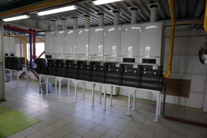
Once the loads and redundancy requirements have been established, the number of boilers and their individual outputs are selected. One large boiler may provide simpler pipework and fewer items of equipment, but it creates a single point of failure and may have limited ability to serve a low seasonal load. Several boilers improve flexibility and maintainability while increasing the number of valves, connections, control devices and service operations.
The boiler cascade is selected so that the available combinations cover the base, peak, transitional and minimum summer conditions. The step between capacity stages matters as much as the total nameplate output. If bringing on the next boiler creates an excessive surplus, the temperature quickly reaches its set-point, the boiler stops and short cycling results.
The minimum cascade output is governed by the lowest stable output of the boiler or boiler combination that must remain in operation under the adopted hydraulic arrangement. It is compared with the lowest sustained load rather than annual average consumption. This check is particularly important in summer, when only domestic hot water or a small process circuit may be operating.
Burner modulation or electric-stage range should not be assessed separately from the system. Stability also depends on water volume, network inertia, minimum flow through the boiler, return-water temperature, hydraulic separation and the rate of load change. Even a wide published modulation range will not prevent short cycling if a sensor is positioned poorly or the circuit has insufficient energy storage.
The cascade-control sequence defines boiler staging, lead-boiler rotation, hysteresis, minimum run time and the pause before restarting. Rotation balances operating hours, while timing constraints prevent the controls from reacting to every short fluctuation. Variable-speed pump control must be coordinated with the permissible boiler flows and the actual opening of the consumer circuits.
A buffer vessel can lengthen the operating cycle and absorb a short surplus of heat, but its volume is calculated from the difference between minimum source output and load, the usable temperature range and the required run time. Installing a buffer without correcting unsuitable set-points or hydraulic design conceals the cause rather than removing it.
Options should be compared over seasonal operation rather than by rated-point efficiency alone. Part-load performance, number of starts, auxiliary consumption, temperature schedule, service outages and reserve availability are all relevant. A configuration with greater installed capacity does not necessarily provide better actual efficiency or reliability.
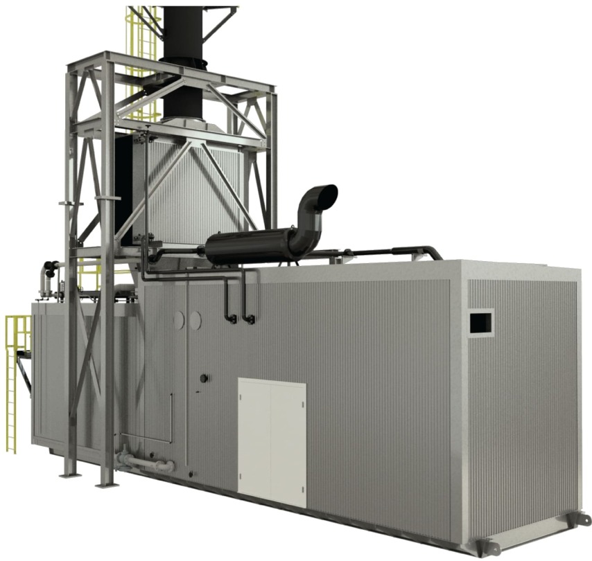
The final cascade is also checked against the space available within the module, equipment delivery and replacement routes, flues, ventilation, fuel handling, electrical incomers and pump sets. The layout must allow each unit to be serviced safely. If a boiler cannot physically be removed or isolated without stopping the entire heat source, the formal reserve loses part of its practical value.
Input data required for selection and verification of the result
Calculation quality is determined by the quality of the input data. A new facility uses design loads from the related disciplines, while a refurbishment supplements them with a survey and verified metering. Where information is missing, assumptions are recorded separately so that the client understands their effect and can refine the result.
The following information is normally required to prepare the heat balance:
- building plans, envelope characteristics or completed design-load calculations;
- site location, internal temperatures and room operating schedules;
- outdoor-air flow rates, ventilation modes and heat-recovery information;
- domestic-hot-water, process and intermittent-peak profiles;
- temperature schedules, pressures, connection arrangements and heat-network characteristics;
- available fuel, heat and water metering data with an explanation of the relevant operating conditions;
- available fuels, gas and electricity connection conditions, and backup-fuel storage arrangements;
- permitted interruptions, critical consumers, expansion plans and redundancy requirements.
The result should be a load balance across the design operating cases rather than one isolated figure. It identifies useful consumer demand, network losses, boiler-plant requirements, adopted diversity, the influence of thermal storage and the load that must be retained during a failure. This provides the basis for comparing boiler number and output, turndown ranges and cascade-control strategies.
For a refurbishment, the calculated maximum is checked against measured information, but the model should not be forced to match unverified consumption. Excessive temperatures, leakage, defective control or a changed production programme can distort historical data. Normal operation is first separated from faults, after which the losses likely to remain following modernisation can be identified.
The design result is tested at limiting and intermediate conditions: whether the winter maximum is covered, whether the reserve is sufficient, whether the smallest stage can operate steadily in summer, whether the external utilities are adequate and whether permissible network conditions are maintained. Start-up, shutdown, fuel changeover and taking a boiler out of service are analysed separately.
During commissioning, the calculated control philosophy is confirmed on the installed equipment. Set-points, boiler staging and rotation, minimum run times, pump control and response to changing load are adjusted. Actual trends for temperatures, output, flows and start frequency allow the sequence to be refined without changing the justified system structure.
TeploFormat Engineering can prepare the heat balance, compare boiler configurations and coordinate them with the fuel facilities, hydraulics, automation and module layout. For a turnkey boiler plant, redundancy and acceptance criteria are agreed before equipment selection so that the client receives a workable system for every required mode rather than the greatest possible sum of nameplate capacities.
Therefore, a modular boiler plant capacity calculation must be based on separate loads, verified diversity, a defined set of design operating cases and clear reliability requirements. Boiler number, individual output and modulation range are checked as one cascade, from the winter maximum down to the lowest sustained load.
To prepare the heat balance, provide TeploFormat Engineering with plans or completed load calculations, operating profiles for heating, ventilation, domestic hot water and processes, metering data, temperature schedules, available energy sources and permitted interruptions. Once the input data have been verified, you can request a calculation and obtain a justified cascade structure with a defined reserve for the particular facility.
A PHP Error was encountered
Severity: Warning
Message: Array to string conversion
Filename: views/details_tpl.php
Line Number: 114
Backtrace:
File: /home/lg353578/tfe.com.ua/www/inner/application/modules/news/views/details_tpl.php
Line: 114
Function: _exception_handler
File: /home/lg353578/tfe.com.ua/www/inner/application/third_party/MX/Loader.php
Line: 322
Function: include
File: /home/lg353578/tfe.com.ua/www/inner/application/third_party/MX/Loader.php
Line: 270
Function: _ci_load
File: /home/lg353578/tfe.com.ua/www/inner/application/modules/news/controllers/news.php
Line: 349
Function: view
File: /home/lg353578/tfe.com.ua/www/inner/application/third_party/MX/Modules.php
Line: 71
Function: details
File: /home/lg353578/tfe.com.ua/www/inner/application/controllers/init.php
Line: 144
Function: run
File: /home/lg353578/tfe.com.ua/www/index.php
Line: 339
Function: require_once