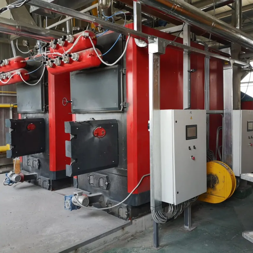
Modular boiler plant for pellets and wood chips: how to design reliable fuel feeding
A modular boiler plant for pellets and wood chips will operate reliably only when its fuel storage, discharge and conveying systems match the actual characteristics of the biomass. Selecting the boiler alone is not enough: material bridging in the store, inconsistent metering or a blockage upstream of the furnace can restrict the output of the entire plant.
The final arrangement is determined from fuel analysis, the delivery method, required operating autonomy, site geometry, heat-load profiles and equipment manufacturers’ requirements. General engineering principles help to prepare the input data, but they do not replace project-specific calculations.
Why a modular boiler plant for pellets and wood chips needs different equipment
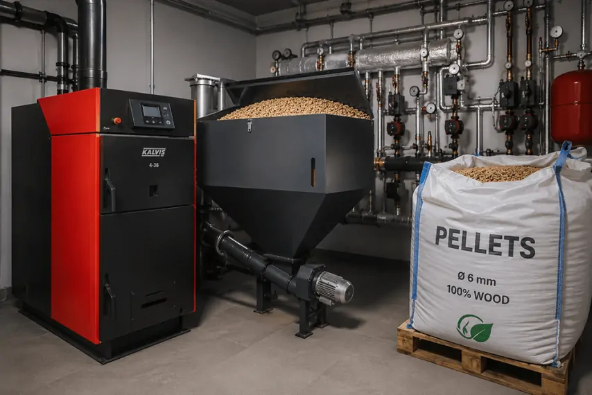
Pellets normally have a more consistent shape and more predictable flow properties, which simplifies conveying and metering. However, repeated transfers can break the granules, create fines and dust, while exposure to moisture can reduce their strength and cause them to compact. A pellet-fired boiler plant therefore needs not only a suitable hopper but also a carefully organised route from fuel reception to the furnace.
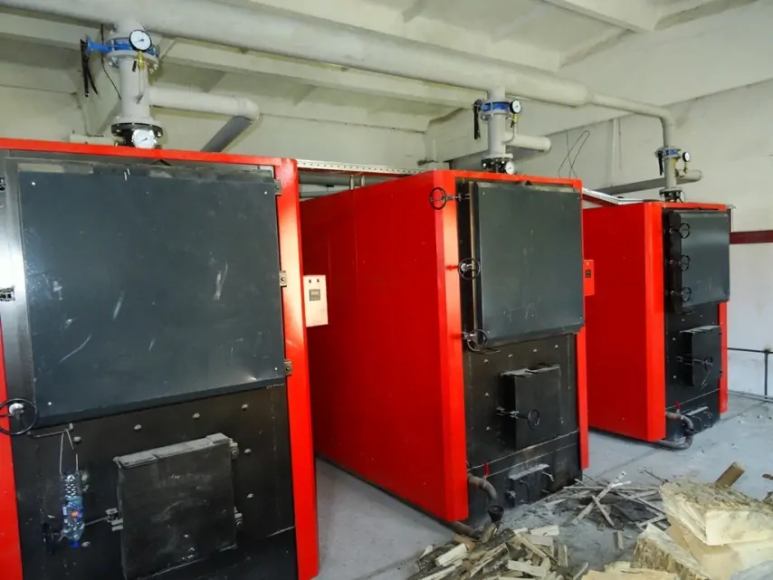
Wood chips vary much more significantly from one delivery to another. Their behaviour is affected by moisture content, particle length and thickness, the amount of bark, fines and foreign material, as well as bulk density. Long pieces can interlock, form bridges above the extractor, jam gates or enter the metering device in an inconsistent flow.
Pellets and wood chips cannot therefore be treated as interchangeable simply because both are biomass fuels. Even with similar heating values, they impose different loads on the store, drives, screw conveyors, sensors and combustion equipment. If several feedstocks are planned, the suitability of each one must be assessed across the entire process chain, not only against the boiler specification.
The fuel specification should define permitted ranges for moisture, particle size, bulk density, ash content, fines and contaminants. A single average value is insufficient because seasonal changes or a new supplier can alter the performance of the conveying system. Sampling and reception checks should also be defined so that each delivered batch complies with the requirements of the boiler and auxiliary equipment.
The configuration of a solid-fuel boiler plant is coordinated with the technical documentation for the boiler, furnace, conveyors and extraction equipment. If the permitted fuel characteristics are not agreed before equipment is ordered, it may later be difficult to distinguish a fuel-related problem from incorrect commissioning or operation.
Biomass storage, fuel reception and discharge
Storage design begins with the fuel-delivery arrangement. Pellets may be loaded pneumatically or mechanically, while wood chips are more commonly delivered by a tipper vehicle, a walking-floor trailer, a recessed reception pit or another method suited to the site. The reception method affects the height and location of the store, dust generation, unloading time and vehicle access.
Capacity is based on the usable fuel reserve rather than the geometric volume of the structure. The calculation considers fuel consumption, bulk density, the delivery schedule, required autonomy, uneven filling and the space needed for the extraction equipment to operate. Vehicle turning, winter operation and the procedure for dealing with a delivery that cannot be unloaded through the normal route are assessed separately.
The geometry of the store should minimise dead zones, but there is no universal wall angle or floor arrangement for every biomass fuel. The solution depends on flow properties, particle size, moisture and extractor design. Protection against precipitation and ground moisture, ventilation, drainage, removal of spillages and safe inspection access must also be provided.
Fuel can be discharged using spring agitators, walking floors, hydraulic pushers, screw conveyors or other mechanisms. Selection depends on the storage area, fuel depth, material properties and required throughput. A solution that produces a steady flow of dry pellets may overload or leave substantial undischarged areas when handling wet wood chips.
The mechanism must do more than move fuel: it should operate without severe load peaks. The design therefore assesses bridging, material hang-up and compaction, as well as the entry of foreign objects. When arranging a modular boiler plant, service passages, inspection hatches and a means of isolating individual equipment before cleaning or repair must be retained.
Boiler plant fuel feeding: conveying, hopper storage and metering
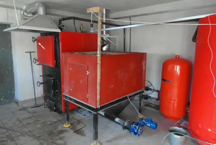
A typical route includes the main-store extractor, one or more conveyors, an intermediate solid-fuel hopper, a metering feeder and the combustion system. Every transfer between mechanisms changes the material flow, so drop heights, throughput, overfill protection and access to likely blockage points must be coordinated.
The capacity of the fuel-handling line is related to the maximum calculated fuel rate and the boiler operating modes. Consumption depends not only on heat output but also on the actual lower heating value, moisture, the efficiency of the selected equipment and the required turndown range. The design establishes an appropriate capacity margin: an oversized conveyor can impair metering accuracy just as insufficient throughput can restrict boiler load.
Screw-type fuel feeding is useful for controlled movement of bulk material, but screw diameter cannot be selected from boiler output alone. The largest permitted particle, route length, angle of inclination, rotational speed, trough filling, starting under load and required torque all need to be considered. Long pieces and bark are particularly important with wood chips because they can jam clearances or wrap around moving components.
Complex routes may use a sequence of screw, chain, scraper or other conveyors. The number of transfer points should be justified because each one increases dust generation, pellet degradation and the number of potential failure locations. A wood-chip-fired boiler plant also needs a route that allows larger pieces to pass without constrictions where material can accumulate.
The intermediate hopper decouples the main-store extraction system from the precise furnace feeder. It provides a short-term reserve and helps stabilise fuel feeding, but requires high- and low-level monitoring, overfill protection and a coordinated filling sequence. Its geometry is selected to prevent material from hanging above the outlet or entering the metering device in uncontrolled batches.
Fuel metering must follow the demand from the combustion control system throughout the operating range. An inconsistent fuel flow forces the controls to make continuous air adjustments, reduces temperature stability and may increase unburnt material. The conveyors, metering feeder, furnace and combustion-air control are therefore tested as one connected process.
Burn-back protection, controls and service
Functional fire separation is required between the fuel store and the furnace. Depending on the design, this may include rotary or isolating devices, a break in the fuel stream, temperature monitoring, an extinguishing system or a combination of measures. A single component cannot automatically be regarded as sufficient for every arrangement; the solution must be coordinated with the equipment manufacturers and the requirements applicable to the facility.
The controls must do more than stop a drive when an alarm is received: they must place the process line in a safe state. The required sequence depends on where the hazard is detected, the fuel remaining in the conveyors, furnace inertia and the design of the protective devices. Fuel feeding should not restart automatically after a safety trip until the cause has been established and the conditions for restarting have been confirmed.
Monitoring can include hopper-level sensors, shaft-rotation or chain-motion detection, drive-current monitoring, temperature sensors, gate-position switches and other instruments specified by the project. Their signals should identify a clear root cause rather than provide only a general fault alarm. This reduces diagnostic time and helps prevent repeated attempts to start a blocked mechanism.
The control logic covers sequential conveyor starting, hopper filling and emptying, fuel metering, blockage monitoring, normal and emergency shutdown, and the response to a power failure. Reversing or automatic restart is permitted only where it is supported by the equipment design and does not create a risk to personnel or machinery.
A blockage must not be cleared while mechanisms are moving. The design should provide for stopping the equipment, isolating energy sources, preventing unintended restart and safely accessing the affected section. The cleaning procedure is recorded in the operating documentation, and personnel are trained to distinguish routine maintenance from emergency intervention.
Redundancy for critical drives and the stock of spare parts are determined from the consequences of failure, acceptable downtime and component lead times. Boiler plant warranty and service should be considered during design so that equipment remains accessible and consumable parts can be replaced without dismantling a substantial part of the system.
The general regulatory framework for the design is established by DBN V.2.5-77:2014 “Boiler Houses”. Fire-safety, construction, operating and environmental requirements are then determined for the specific site, fuel, heat-carrier parameters, equipment and type of construction work.
Testing the system with representative fuel
Even a correctly calculated system must be verified during commissioning. Testing should use a representative batch with characteristics close to those expected in normal operation. Testing a wood-chip boiler plant only with consistent reference pellets does not demonstrate that its storage and conveying equipment is ready to handle the actual wood chips.
The tests assess minimum and maximum throughput, starting under load, normal shutdowns, hopper refilling and metering stability. High-level, empty-hopper, conveyor-stop, drive-overload and high-temperature signals are simulated separately. The objective is not merely to demonstrate that fuel can pass through the system once, but to verify the predictable response of the complete plant.
The results are used to record the permitted fuel characteristics, sensor and drive settings, start and stop sequences, conditions for manual intervention and required inspection procedures. This information is included in the operating instructions and reflected in the fuel-supply agreement. If a feedstock falls outside the agreed limits, the need for adjustment or component replacement should be assessed before it is loaded into the store.
Before design begins, the customer should prepare:
- pellet or wood-chip analysis showing the ranges for moisture, particle size, ash content, density and contaminants;
- details of delivery vehicles, unloading method, delivery schedule and required operating autonomy;
- a site plan showing vehicle routes and the areas available for storage, modules and service access;
- the heat-load profile, minimum operating modes and redundancy requirements;
- responsibility boundaries for civil works, power supply, fire-safety systems and operation.
Comparing the input data with completed boiler plant projects helps illustrate possible approaches, but it does not turn a preliminary arrangement into a finished design. Even for a turnkey boiler plant, conveyor capacity, usable storage volume, protective systems and control parameters must be determined for the specific facility.
Therefore, a modular boiler plant for pellets and wood chips needs a coordinated process chain from fuel reception to accurate furnace feeding, not a universal screw conveyor. Reliable operation depends on a clear fuel specification, properly organised storage, predictable conveyor performance, functional fire separation and testing with representative fuel.
Send the fuel analysis, logistics arrangement and required autonomy to the engineers at TeploFormat Engineering to discuss the project and select a fuel-feeding system that reflects the operating modes, site conditions and requirements of the chosen equipment.