Solid-fuel modular boiler plant: fuel, storage and thermal circuit requirements
A solid-fuel modular boiler plant begins with a fuel specification and a clear logistics concept. If moisture content, particle size or ash content differs from the design data, the result can affect output, combustion, emissions, ash volumes and equipment life.
Fuel storage and handling, the furnace, thermal circuit, ash removal and flue gas discharge must be designed as one integrated system. Their parameters are determined from fuel analysis, the heat-load profile, site conditions and manufacturers’ requirements.
Fuel as the primary design input
It is not enough to specify only pellets, wood chips, logs, briquettes or agricultural residues. The fuel specification should state the lower heating value, moisture content, particle-size range, bulk density, ash content, permitted contaminants and tendency to compact or form bridges.
Seasonal variation matters as much as average values. Wetter material reduces useful heat output, inconsistent sizing disrupts metering, and high ash content increases the load on boiler cleaning, ash removal and flue gas cleaning equipment.
A claim that a boiler can operate on any biomass is technically misleading. The configuration of a solid-fuel boiler plant is selected for a defined fuel specification, while any change to another feedstock must be assessed separately.
Fuel reception, storage and operating reserve
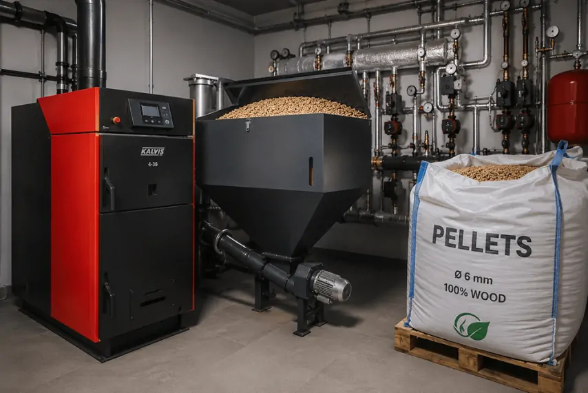
Boiler plant fuel storage is sized together with the logistics system. The design considers delivery vehicles, unloading, delivery frequency, access for handling equipment, the required operating autonomy and site restrictions. Pedestrian and vehicle movements are separated in accordance with the project.
Capacity is calculated from consumption, autonomy, bulk density and usable fill. Geometric volume is not the same as available reserve: part of the space is needed for loading, extractor operation, access and maintenance.
The storage design also considers protection from precipitation and ground moisture, ventilation, dust, self-heating potential, spillage removal and fire scenarios. The solution depends on the properties of the actual fuel, the storage method and the requirements applicable to the facility.
Fuel handling system
A typical process route may run from storage through an agitator or extractor, conveyor, intermediate hopper and metering device to the furnace. The actual arrangement is selected according to particle size, flow properties, capacity, route length, elevation changes and the required level of redundancy.
The design must account for material hang-ups, bridging, foreign objects, drive overload and conveyor failure. It therefore includes level, motion and load monitoring, access for cleaning and safe procedures for clearing blockages.
A separate objective is to prevent fire from travelling back from the furnace towards the store. Fire separation, temperature monitoring and the emergency shutdown sequence depend on the feeder design and manufacturer’s documentation. Working on a blocked mechanism without stopping and isolating it creates an additional hazard.
Boiler, furnace and operating range
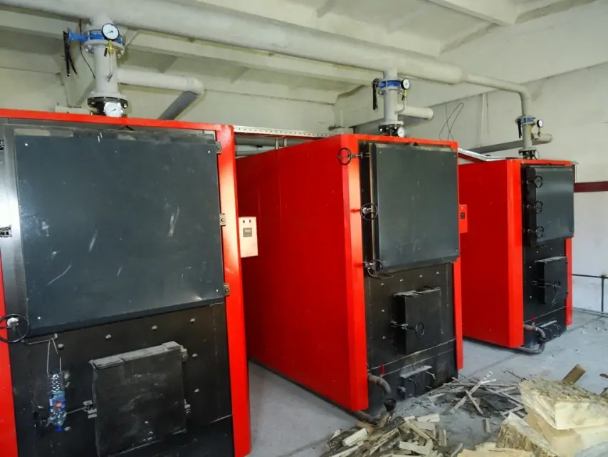
The furnace is matched to the fuel type, particle size, moisture and ash content, as well as the behaviour of ash at high temperatures. Equipment that burns consistent pellets reliably will not necessarily perform in the same way with variable-moisture wood chips or agricultural biomass.
Selection covers rated output, minimum stable load, turndown range and combustion inertia. Heat continues to be released from material in the furnace after fuel feeding stops, so the thermal circuit and control system must provide controlled removal of residual heat.
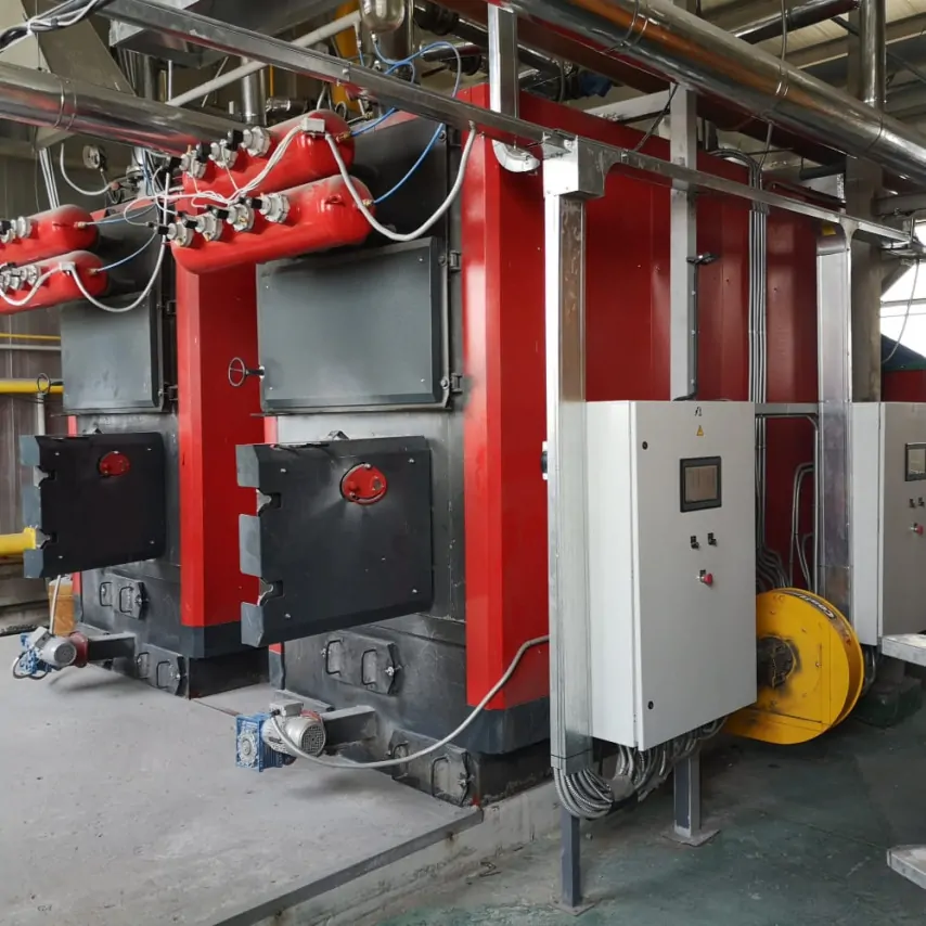
The module layout must provide access to the furnace, drives, ash-removal areas and heating surfaces. Regular cleaning affects heat transfer and gas-path resistance, so the design must allow this work to be completed without unsafe operations.
Solid-fuel boiler plant thermal circuit and equipment protection
The boiler circuit is coordinated with pumps, return-water mixing, hydraulic separation and consumer circuits. There is no universal minimum return temperature: it is set by the project and the boiler manufacturer’s requirements to limit the risk of low-temperature corrosion.
A buffer vessel can absorb surplus heat, reduce cycling and stabilise boiler operation. Whether it is needed, and its required volume, depend on furnace inertia, minimum load, the demand profile and control method. There is no universal arrangement.
Protection against overheating, insufficient circulation and power failure is considered separately. If the facility needs another heat source for standby or peak operation, the suitability of a multi-fuel boiler plant is assessed against the heat-load profile and available energy sources.
Ash removal, flue gas cleaning and discharge
The ash removal system is sized from fuel consumption and ash content, operating mode and furnace characteristics. The design covers ash collection, cooling, conveying and temporary storage, taking account of dust, hot particles, mechanism maintenance and subsequent waste handling.
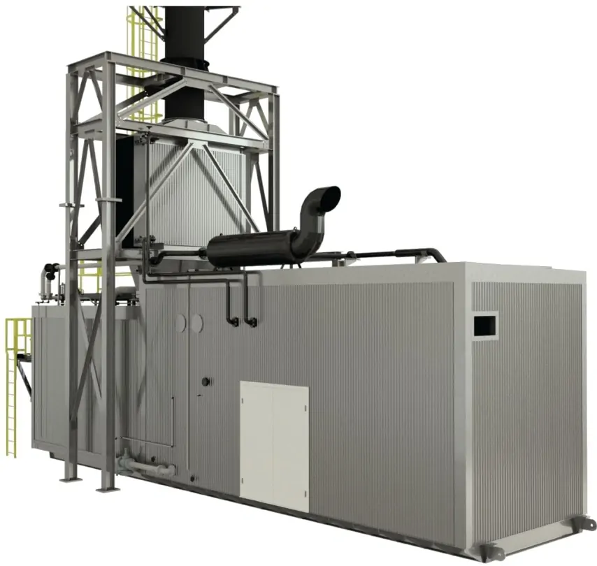
Flue gas cleaning equipment is selected according to the fuel, output, boiler parameters, flue gas composition and applicable emission requirements. A single filter type cannot be treated as a universal solution for every biomass boiler plant.
The induced-draught fan, flue-gas ducts, chimney and controls are considered together. Resistance changes as deposits accumulate, affecting draught and combustion, so negative-pressure monitoring and suitable inspection and cleaning points are required. The general regulatory framework is established by DBN V.2.5-77:2014 “Boiler Houses”, while environmental procedures are determined for the particular emission sources and fuel.
Controls, redundancy and personnel
The control system coordinates the start and stop sequence of mechanisms, fuel and air metering, pump operation, draught, boiler cascade and buffer charging. Where suitable equipment is installed, flue-gas oxygen monitoring may be used to adjust combustion, but it does not replace other safety functions.
Critical drives, sensors and spare parts are specified according to the consequences of failure and the acceptable downtime. The design should also provide safe access for cleaning and repair, with clear indication of the root cause of a shutdown.
Personnel involvement depends on the fuel, reception method, automation, installed equipment and operating rules. Even an automated system requires inspections, stock replenishment, ash removal and maintenance. Operating schedules and subsequent warranty and service are agreed in accordance with the contract and manufacturers’ instructions.
Customer input data checklist
- fuel analysis reports, permitted variations and a list of suppliers;
- delivery vehicle type, delivery schedule, unloading method and required storage autonomy;
- heat loads, temperature schedule, minimum operating modes and standby requirements;
- available electrical capacity, water and space for the store, modules, chimney and ash;
- responsibility boundaries for civil works, conveyors, fire systems and operation.
These data are required before a boiler model is selected. When developing a modular boiler plant, they help align the equipment with site logistics and actual heat-supply operating modes.
Therefore, a solid-fuel modular boiler plant operates reliably when fuel properties, usable storage reserve, the fuel handling system, furnace and thermal circuit are calculated as interdependent elements. Numerical parameters and the final equipment arrangement must be determined from project-specific data, not from a universal standard scheme.
Send the fuel characteristics and heat-load profile to the engineers at TeploFormat Engineering to discuss the project and select a safe concept for fuel storage and handling, the furnace and the thermal circuit.